C4 model
Natural way to model software architecture
Hi, this time I have a real treat for you.
If you’re into architecture and diagraming,
If you want to know how to simply represent and effectively communicate your system’s structure,
If you’re open to explore other options than UML,
You’re at the right place.
Pour some coffee, or a tea - whatever you prefer and enjoy :)
Let me draw it for you
We draw diagrams to communicate. It’s yet another way of sending a message to help receiver understand the idea better.
Different levels of abstraction allow us to show or hide certain parts of a system or idea that we want to communicate. We might want to abstract more or less depending on what we want to communicate or to whom we want to communicate.
So, important differentiators are:
- audience - to whom we want to communicate
- idea - what we want to communicate
If you look at it, it’s just like verbal communication. With our words we try to convey the meaning that someone on the other side will understand.
If you get a question: what did you do at work? - you won’t communicate the answer the same way to your colleague, wife or a kid. Depending on what you want to communicate, with how many details, to whom - message will appear different.
How many rules are enough
I can draw an arbitrary diagram with my own rules and explain that to you. You would understand it and message would be successfully received, the way I wanted. That would be okay if it’s just us, but situation gets more complex when we want to share this with more people.
Not just that, we might not even be here at some point and those that read it after us should be able to understand as well.
You can lookup so many different diagrams online, with different shapes, colors, intentions - most of them are understood only by the authors.
That’s why we need some set of common rules to agree upon so that the idea is understood by many not just a few.
But we already have UML right? Well, how many of you are using UML? How many of you are sticking to all the notations UML dictates? Exactly - we strive to simplify things. Most of us went into a direction of using just boxes and lines.
What if I tell you that we can still have only a handful of “rules” and yet a powerful solution.
Reminds me of 20/80 principle. Introducing 20% of the concepts we have in UML in one form or another to cover 80% of the scenarios that we usually tackle.
Anyway, back to the story…
C4 Model
Diagram model that reflects the ideas mentioned above would be C4.
I prefer C4 model as it provides a natural way to view a system.
Starting with the highest levels of abstraction and zooming in into the details, if needed.
It breathes simplicity.
If you think about it, we do that all the time when designing and abstracting details on the code level. We do that to lower the cognitive complexity of the code and make it easier to read and reason.
It’s the same with diagrams.
Simon, the author of C4 model, argues that a common set of abstractions is more important than a common notation. When modeling, model abstraction first and notation second!
So what C4 model actually is?
Simon described it as four levels of diagrams that translate to four levels of abstraction in which we can observe a software system.
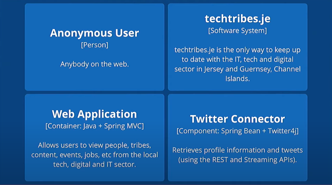
A software system is made up of one or more containers (applications and data stores), each of which contains one or more components, which in turn are implemented by one or more code elements (classes, interfaces, objects, functions, etc). And people (actors, roles, personas, named individuals, etc) use the software systems that we build.
System Context
→ the system, plus users and system dependencies. Focus is NOT on technologies.
Related to:
- who’s using the system (roles, personas)
- where system gets information from, what are the dependencies
- where system sends information to, again dependencies
Audience: everyone, even non technical people
The author of C4 points out that the System Context is “owned” by the team. So in case if you have multiple teams, each responsible for a system subset or a microservice, those out of your control would be dependencies to your system.
I would argue that even though you’re not currently owning a service, but there is one team mindset and still holistic team (department, company) owns the system - you can look at it holistically and model the diagram as you own it - if you as a team have insight into the system overall.
Containers
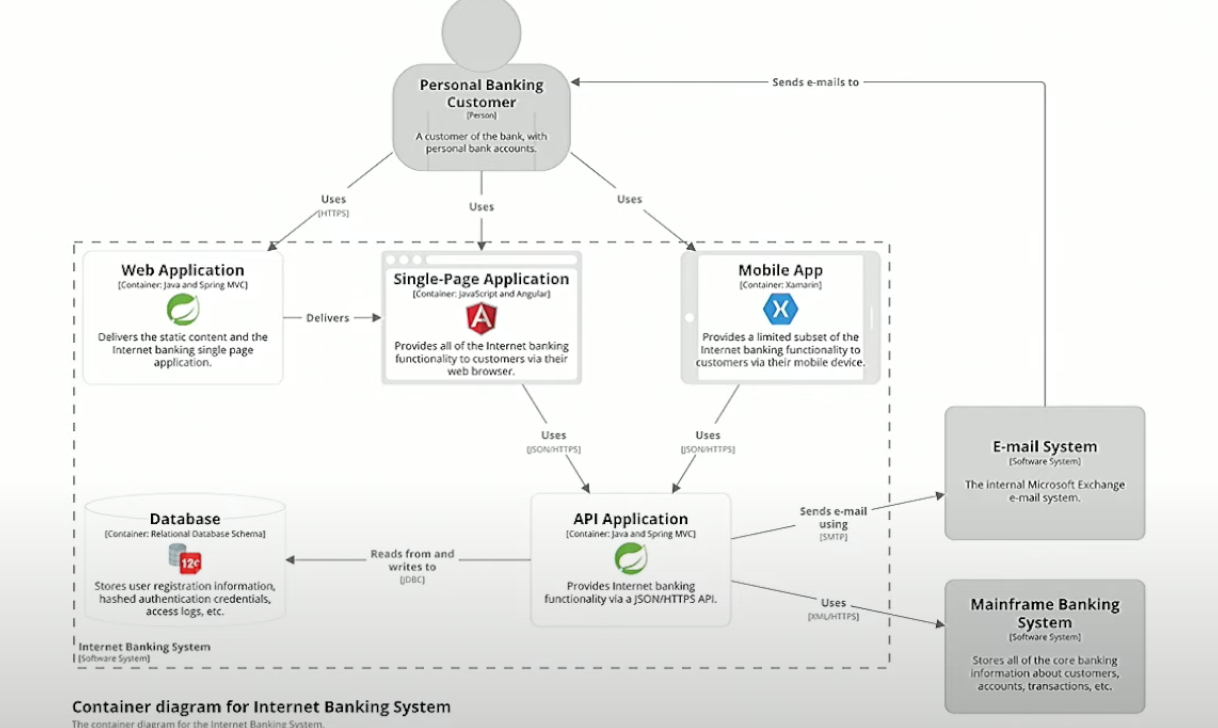
→ Application or a data store. The overall shape of the architecture and technology choices Closest to look at it is a runtime boundary. Deployable units
Related to:
- we might have different kinds of apps (web, mobile etc)
- APIs
- database
- shell script
- Cloud services
Audience: Technical people including devs, architects, Ops
Components
→ A grouping of related functionality encapsulated behind a well-defined interface.
Logical components and their interactions within a container (Zoom and filter)
Related to: Services, Repositories, Controllers, Facade…
Unlike containers, components are not deployable units. All components are part of the same process, container process.
Simon argues that should exclude domain classes and util ones.
In essence, we’re grouping the classes and interfaces into components to form units of related functionality.
Audience: Architects and Devs
Code (not recommended)
→ component implementation details (Details on demand). This is the level of classes, interfaces, functions etc
Code level is not recommended as it gets obsolete easily and can be easily just generated through an IDE.
Audience: Architects and Devs
Those abstractions can be used in any order to describe your system in different levels of detail.
If we categorize it by the level of details, from less detail/more abstractions to more detail / less abstractions:
- Overview first (System context and Containers)
- Zoom and filter (Components)
- Details on demand (Code)
Simon gave an interesting analogy of maps. Think of this abstractions, levels of details as those that you can see on maps. The overview that you get when you open them, or different levels of details when you zoom in. It’s a map of our system, our code base.
Notation
Although C4 model is notation independent and doesn’t prescribe any particular notation it gives some recommendations:
Titles
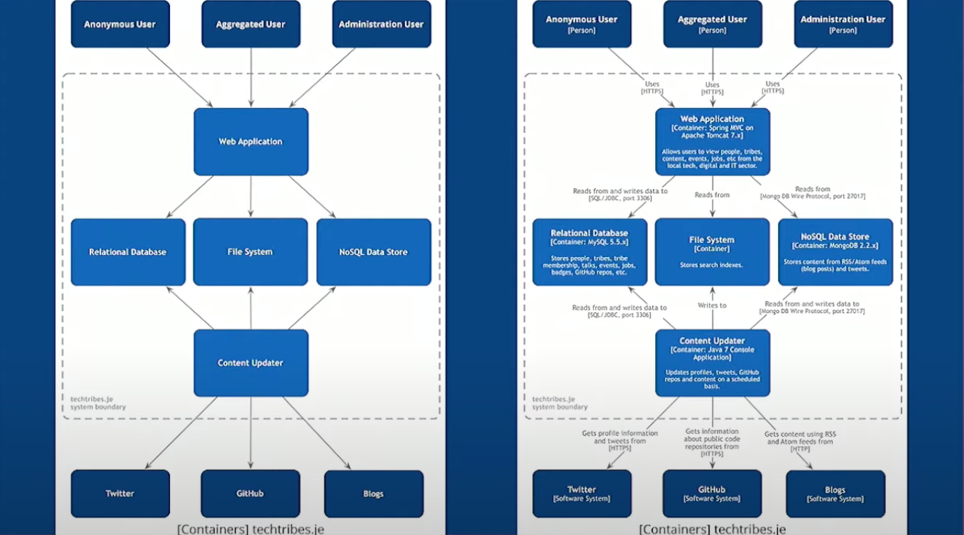
→ put titles on pictures. Short and meaningful [System Context] Financial Risk System
Visual consistency
→ try to be visually consistent with notation and elements positions
Acronyms
→ be careful with using acronyms as they might not be widely known. Only go for them in case you are certain that the others will know them.
Elements
→ start with simple boxes containing the element name, type and technology and a description / responsibility

Just boxes and lines are not enough to explain the usage/responsibilities

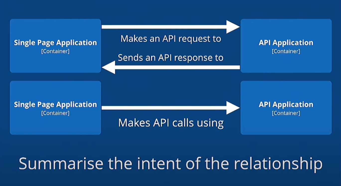
So when using lines, favor uni-directional and show the most important dependencies and data flow and annotation that specifies the purpose of communication.
A → calls → B
A → depends on → B

But be specific, avoid “Uses”, “Makes api call”, “depends on”, “sends message to”
When intents of a relationships are different, use bi-directional (two arrows)
We can also use different lines to describe different relationships (solid for sync, dashed for async communication). We can use colors as well but be careful with that.
We should use shape, color and size to complement a diagram that already makes sense.
Also use icons and other shapes than boxes, they are more pleasing to an eye and self describe the underlying.
But also be careful, as they can also clutter and also make it hard to understand as we might not understand the icons. Example that the author of C4 gave:
![]()
So again, use icons to add on the existing diagram, to add an additional level of information.
Don’t substitute the existing elements.

Here is the checklist you might want to go through to review your c4 diagram: https://c4model.com/diagrams/checklist
Open for extension and adjustment
C4 model gives us a way to visualize the structure. Once we have it, we can use the same concepts to draw other types of diagrams:
- Dynamic/Sequence https://c4model.com/diagrams/dynamic
- Deployment https://c4model.com/diagrams/deployment
- Data
As author of C4 stated:
Although the C4 model provides enough for most software development teams, you should certainly feel that you can add more abstraction levels if you have a genuine need. After all, the agile mindset tells us to “inspect and adapt” in order to improve the way that we work.
C4 is as general as possible, providing levels of abstractions and most common notations that we might need. If that doesn’t fit our needs we can also adapt it, modify it.
Tools
Tools that the Simon does or doesn’t recommend:
- Do not use Visio, draw.io, lucidchart, gliffy because, as Simon explained they are general purpose diagram tools and they do not know anything about software architecture. They’re most common but worst
- C4-PlantUML
- Structurizr - Simons tooling
More on tooling and the way author of C4 reasons on the choices: https://c4model.com/tooling
Conclusion
That would be all for today.
I hope you enjoyed and learned something useful today.
I tried to stay true to the source and give credits to Simon as much as possible and pass the ideas with the flavor of my perspective.
Until next time :)